Because customers need to simplify and economize on space, many networking companies are being asked to move beyond traditional networks and look at ways to combine networking and power management. You’ve got devices that need to share data, but they also need to be powered. If you are looking at a mobile military platform, Power over Ethernet (PoE) simplifies cabling and reduces the number of devices needed on a platform.
The same thing is applicable to dismounted soldiers. But they come with an added challenge: different devices from different manufacturers—all needing to communicate with each other—using USB or Ethernet. They all also need power but use portable batteries every one of them—and this creates a dilemma. Weight, battery management, ongoing power needs. All challenges for the dismounted soldier.
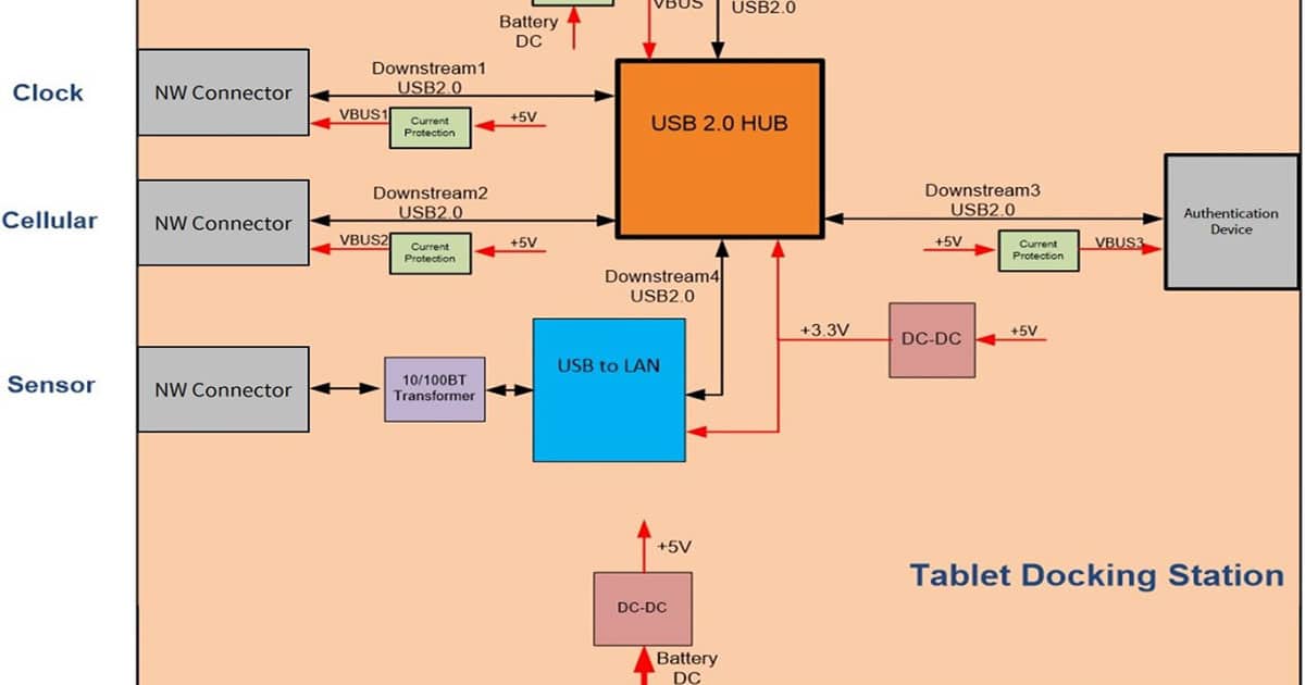
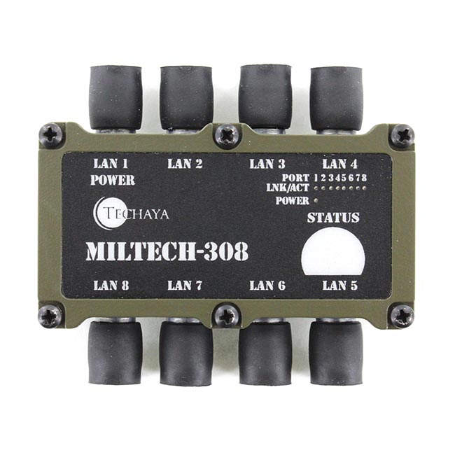
New products, known as Integrated Soldier Power and Data Management (ISPDS)—or as Soldier Worn Power and Data Hub, Tactical Soldier System, and several other terms–enable both simultaneous data networking between the soldier-carry communications devices and the power management to keep the devices running. They are a combination of data and power management, easing the burden of the number of batteries and cabling (and therefore weight) soldiers must carry. Knowing that power management has its own “language” just as data communication does, we thought we would take a few minutes to talk about power management protocols and how they work.
The primary protocol used to manage power on computing device is SMBus. But what is SMBus and what functions does it manage? At the basic level, a bus is a communications system that transfers data between two components on the motherboard of a computer or between two computers. Typically, it manages low-speed management communications to power-related chips such as a battery subsystem, but other system level devices might include temperature, fan, voltage sensors, lid switches and clock chips. Computer buses can use both parallel and bit serial connections and can be wired in a multidrop (electrical parallel), daisy chain topology or connected by switched hubs.
To read more Ethernet blogs from Ronen Isaac, click here.
Just like Ethernet, SMBus consists of both the physical layer and the protocol layer. The physical layer is based on IC2 Bus (which is a synchronous, multi-master, multi-slave, packet switched, single-ended, serial communication bus) with some extensions. The protocol layer defines classes of data and how that data is structured.
Every SMBus system architecture has a two-wire network. Each device on the network has a unique address so other devices can find and communicate directly with it. These two wires are comprised of one SDA (serial data) and SLC (serial clock). Transfers of data are initiated by the master device. If another device recognizes the call and responds, it becomes a slave. Just as in Ethernet networks, data transfers go through a sequence of START (initiate a transfer), STOP (ends a transfer), ACKNOWLEDGE (ready for transfer), NOT ACKNOWLEDGE (not ready for transfer). There is additional arbitration, read/write, and other functionality that also take place here.
For the battery subsystem, the motherboard uses SMBus to communicate with the battery to garner battery information that is critical to uptime including:
- – Manufacturer information
- – Model/part number
- – State of charge
- – Current
- – Voltage
- – Notification to save data on the motherboard, in anticipation of a suspend event (i.e. sleep, powersave, etc.)
- – Report different types of errors
- – Accept control parameters
Today’s Smart Battery Systems (SBS) are usually comprised of a host, a smart battery and a smart charger. Each device within this system communicates using the SMBus protocol. In the SBS, the battery can tell the charger its battery chemistry type, its capacity, how it wants to be charged, its optimal charging current, maximum charging time, and so on. With this information, the charger can find the right profile to charge the battery optimally. With an optimal charge profile, the battery does not have to be recharged as frequently as those using systems that only “guess” the battery chemistry. This benefits the end user by providing longer battery life and accurate battery energy capacity information down to the last 1%. In fact, an SBS-compliant design can increase battery cycle life as much as 30%.
In addition, users are not tied to one type of battery technology; different types of battery chemistries can be used interchangeably. Smart Chargers can discover the chemistry of a newly connected battery from its pre-loaded list of profiles (based on the manufacturer, make, and model of the battery already loaded in to the charger) and use the correct charging profile for the chemistry for the new battery. Field personnel can quickly interchange to any available battery without equipment failure and dangerous equipment mismatches.
In short, ISPDS delivers both personal area networking (PAN) and power management in a single device. Each ISPDS can be loaded with firmware for any smart battery a platoon would deploy. SMBus allows ISPDS to read the battery, understand its optimal charging profile, and act accordingly. Using SMBus is the optimal way for ISPDS to provide smart battery management– thus prolonging the life of batteries during a mission.


